
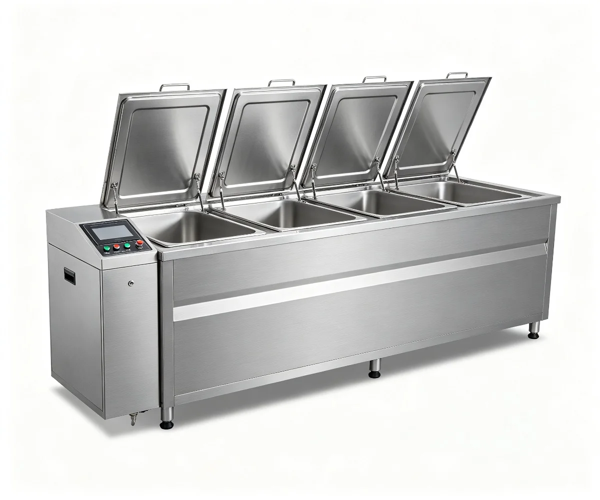
Multi-Stage Systems
Multi-Tank Ultrasonic Cleaning Machine - Clean, Rinse and Dry in One Line
A configurable 2-8+ stage system combining rough wash, fine wash, rinsing, treatment and drying around the required cleanliness target.
View configuration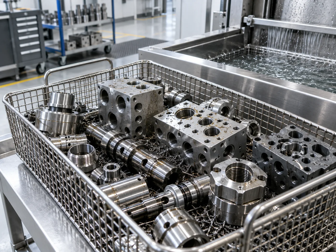
LENJEX Industrial Cleaning
Removes machining oil, particles and burrs from valve, pump and actuator parts, including internal passages.
Why Ultrasonic
Hydraulic and pneumatic components depend on clean internal passages, because particles and residual oil cause valve sticking, wear and performance failures. Ultrasonic cavitation reaches cross-drilled holes, spools, housings and internal features to flush contamination.
The process is commonly run with precision cleanliness control and filtration. A multi-tank system or clean-rinse-dry system suits production, with vacuum cleaning for hard-to-dry assembled parts.
Particle limits and drying are defined early because the components are highly sensitive to contamination.
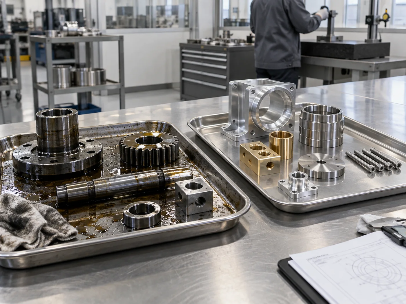
Typical Workpieces
Contamination
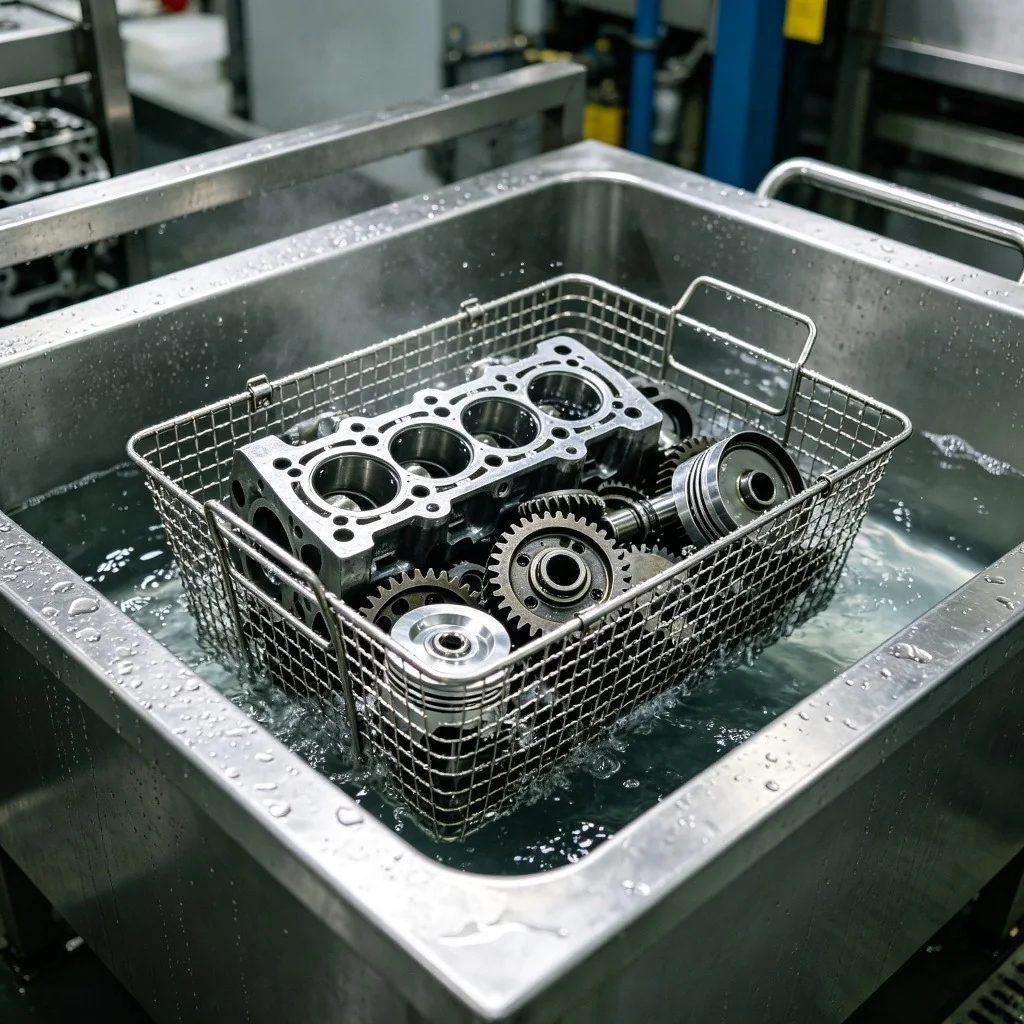
Cleanliness Target
Acceptance is based on particle counts or gravimetric cleanliness linked to the component function.
Drying must be complete in passages and cavities before assembly.
Recommended Sequence
The final sequence depends on soil loading, material, rinse quality and drying behavior.
Recommended Equipment
The final specification follows process testing and production analysis.
Multi-Stage Systems
A configurable 2-8+ stage system combining rough wash, fine wash, rinsing, treatment and drying around the required cleanliness target.
View configuration
Multi-Tank & Automatic Cleaning Systems
Compact multi-stage ultrasonic wash, rinse and drying system
View configuration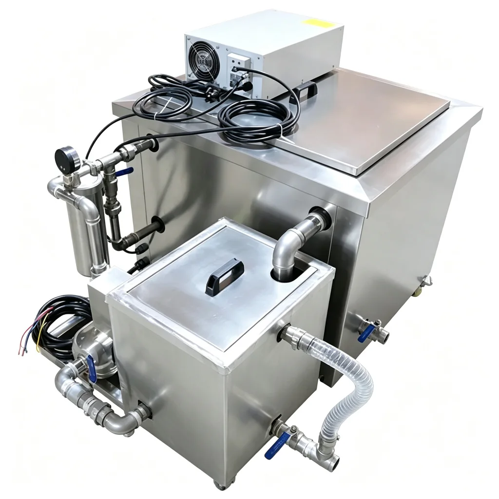
Industrial Single-Tank & Special Cleaners
Sealed vacuum ultrasonic cleaning and drying with hydrocarbon or modified-alcohol solvent
View configurationProcess Controls
Confirm the part, soil, loading and final handling before fixing equipment settings.
Control 01
Record surfaces, cavities and features that can trap air or liquid.
Control 02
Test the heaviest representative contamination, not an ideal sample.
Control 03
Keep acoustic access and part spacing consistent with production.
Control 04
Match downstream handling to residue and corrosion risks.
System Selection
Stage count and automation follow the validated process and required output.
Batch
Compare for focused washing where rinsing and drying are managed separately.
Multi-stage
Add controlled stages when carryover and final condition matter.
Automatic
Evaluate automation when output, handling or recipe control requires it.
Acceptance
Use the same practical inspection method for trial samples and production parts.
Representative Trial
Trial evidence should cover normal production and the most difficult expected condition.
Application Questions
Include normal production parts and the most difficult expected geometry or contamination so the process is not based on an easy sample.
Provide part dimensions, material, soil, cleanliness target, parts per load, required output and available utilities.
Cross-drilled and open passages can be flushed with cavitation and flow; sealed assemblies are validated separately and may need solvent or vacuum processing.
Limits vary by component and customer; LENJEX confirms the inspection method and target before configuring the line.
Hot air handles open parts, while vacuum drying is used for complex passages and assembled components.
Related Applications
Industrial Application
Machined parts often retain cutting fluid and fine chips in cross holes, threads and internal channels where manual washing is inconsistent.
View cleaning approach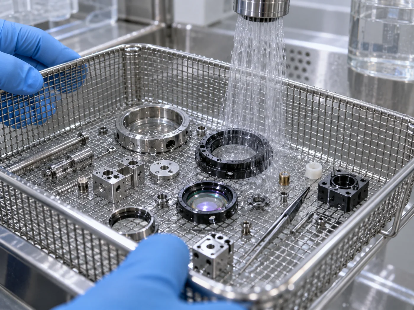
Industrial Application
Precision cleaning is controlled by particle size, surface sensitivity, rinse quality, bath condition and handling after the wash.
View cleaning approach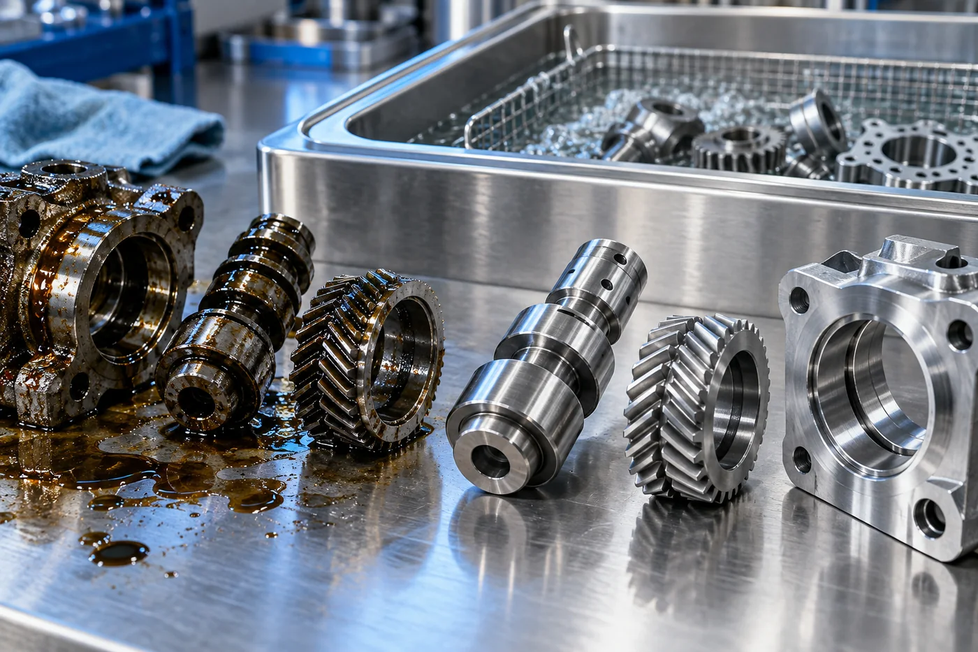
Industrial Application
Removes carbon, oil, casting and machining residues from turbocharger and turbine components.
View cleaning approach